Commercial
Scalable modular roof protection for commercial buildings, warehouses, factories, manufacturing plants and distribution centres.
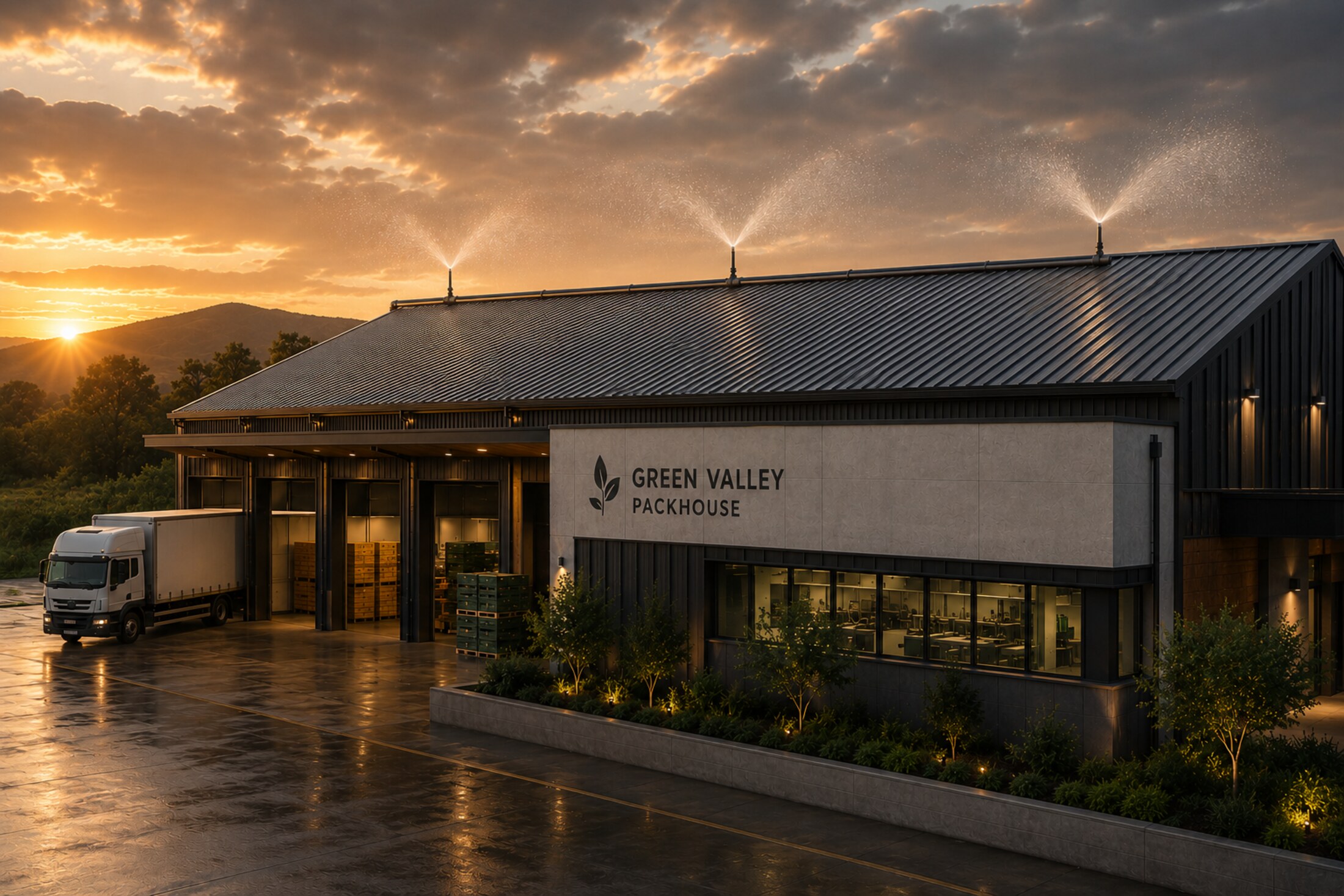
Zoned configuration — COM
Covers commercial buildings, warehouses, factories, manufacturing plants and distribution centres — with scalable, zoned modular roof protection.
Zoned configuration for long commercial rooflines, where modules are grouped into independently valved zones so demand stays inside the site supply.
Use the Rainmaker System Designer to configure the modular platform to your architecture, water source and roofline — the calculator returns module count, layout and pricing in under two minutes.
Specified for these environments.
- Retail centres, offices and mixed-use commercial buildings
- Warehouses and distribution facilities
- Long single-ridge roofs requiring staged activation
- Exposed elevations and boundary walls carrying their own runs
- Summer roof-temperature and cooling-load reduction
- Process-hazard or flammable-liquid fire suppression duties
Specified for commercial conditions.
Only the data relevant to this configuration is listed. Quantities and total flow are confirmed for your property in the Preliminary Protection Design Report.
Module & zone configuration
- Module length
- 6 m (standard part throughout)
- Flexible sprinkler heads per module
- 2
- Zoning
- Independently valved zones, configured per building
- Nominal flow per module
- ≈ 1 500 L/h
- Scaling method
- Add modules and zones — geometry unchanged
Mounting & installation
- Mounting position
- Roof ridge and/or exposed exterior walls
- Bracket
- UV-stabilised PVC ridge or wall bracket
- Fixing method
- Screw-fixed and epoxy bonded to approved surface
- Manifold
- Zone valves grouped at an accessible manifold
- Installation route
- Registered plumber / contractor
Coverage
- Spray radius (per sprinkler head)
- 12 metres
- Coverage strategy
- Continuous overlap maintained within each zone
- Activation
- Zone-by-zone, matched to the exposed elevation
- Protected surfaces
- Roof envelope, parapets, wall faces, perimeter band
Water supply & flow requirements
- Minimum operating pressure
- 2 bar at inlet, per active zone
- Flow planning
- Peak demand calculated on simultaneous zones only
- Typical source
- Municipal main, site tanks or fire reserve
- Booster pump
- Sized to the largest simultaneous zone group
- Control
- Manual zone valves at the manifold
Why this configuration is built the way it is.
- Zoning is the primary engineering tool: it keeps flow within the available supply instead of oversizing the connection.
- One module part number across the building simplifies facilities stores and spares holding.
- The site QR code at the manifold links to the current installation and operating guidance.