Rainmaker® technical reference.
A concise engineering reference for homeowners, architects, engineers, plumbers, contractors, insurers and distributors. Specifications, water supply requirements, diagrams, bill of materials and downloadable data sheets for the Rainmaker® Modular Roof Protection System.
Product Overview
The Rainmaker® Modular Roof Protection System is a South-African-engineered modular protection solution designed for roof ridges and exterior walls. It is straightforward to install as a DIY project using the online Installation Guide and Installation Video accessed via the supplied QR code, or by a registered plumber. When activated, the Rainmaker® system gradually saturates the protected area to help reduce wildfire risk.
Module
6 m
Heads / module
2
Spray radius
12 m per head
Min. pressure
2 bar
Intended applications
- Residential
- Thatch roofs & safari lodges
- Commercial buildings
- Agricultural buildings
- Exterior wall installations
Each application is a distinct configuration of the same 6 m modular chassis. Nozzle selection, mounting method, coverage strategy and water-source assumptions differ per environment — open an application for its own specification set.
System Specifications
- 6 metre modular section
- ✔
- 2 flexible sprinkler heads per module
- ✔
- Spray radius (per sprinkler head)
- 12 metres
- Minimum operating pressure
- 2 bar
- UV-resistant construction
- ✔
- Modular expansion for any roof length
- ✔
- DIY friendly installation
- ✔
- Suitable for registered plumber installation
- ✔
Configuration Matrix by Application
The module, spray radius and minimum operating pressure are common to every configuration. Everything below differs by application, and each application page lists only its own relevant specifications.
| Application | Config | Mounting | Nozzle | Coverage strategy | Typical water source |
|---|---|---|---|---|---|
| Residential | RES | Roof ridge | Standard pressure-regulated | Single continuous run | Municipal / tank |
| Thatch roofs & safari lodges | THA | Thatch crest | High-volume thatch | Both-slope saturation | Borehole / tank + pump |
| Commercial buildings | COM | Ridge + exterior wall | Standard pressure-regulated | Independently valved zones | Municipal main / site tanks |
| Agricultural buildings | AGR | Shed ridge / perimeter posts | Long-throw | Continuous wetted perimeter | Borehole / dam + pump |
| Exterior wall installations | WAL | Exterior wall face | Standard pressure-regulated | Vertical face + ground band | Municipal / tank / borehole |
Water Supply & Flow Requirements
Minimum operating pressure
2 bar
Measured at the system inlet under flowing conditions.
If supply below 2 bar
Inline pump
Install an appropriately sized inline pressure pump to reach the minimum operating pressure.
- Minimum operating pressure
- 2 bar at system inlet
- If supply < 2 bar
- Install appropriately sized inline pressure pump
- Municipal supply
- Compatible
- Borehole
- Compatible
- Water storage tank
- Compatible (gravity or pumped)
- Dam
- Compatible (pumped)
- Reservoir
- Compatible (pumped)
Water flow is scaled by the number of modules and sprinkler heads fitted to the property. The Rainmaker® System Designer returns the expected peak flow, the recommended defensive reservoir size and whether an inline pressure pump is required for the selected water source.
Installation
The Rainmaker® system is designed for straightforward DIY installation. Owners who prefer a professional install may engage a registered plumber; the connection interfaces are standard. Instructions are accessed online via the QR code supplied with every system, so installers always work from the latest guidance.
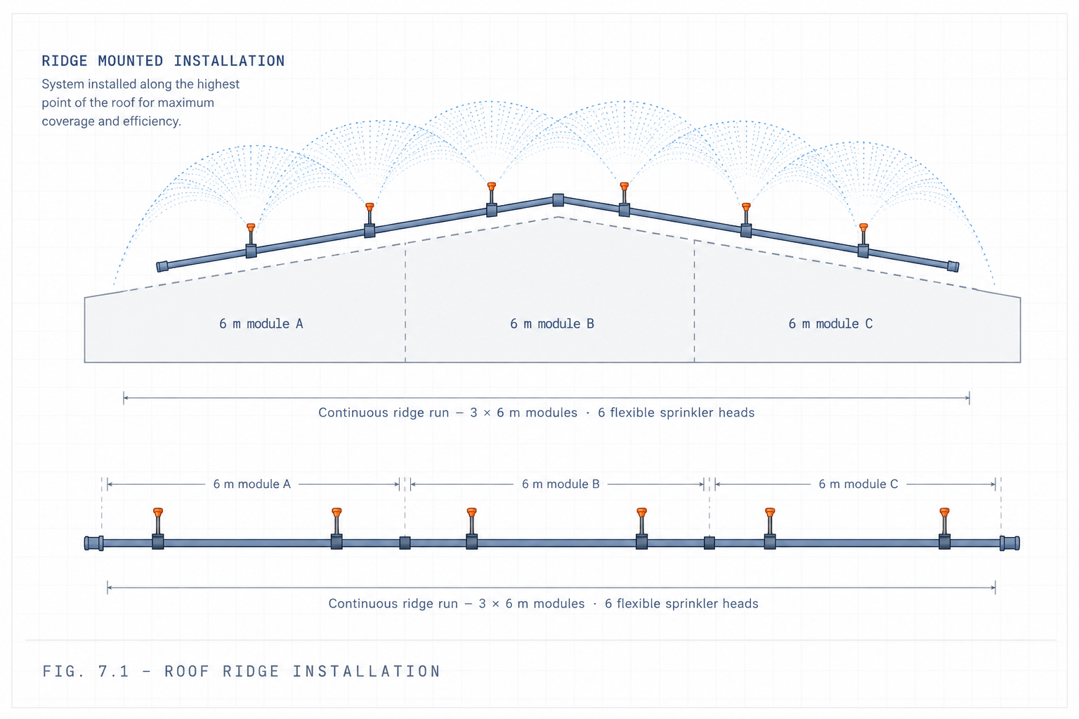
- 01Plan the ridge or wall run in 6 m module increments, running parallel with the ridge for its full length.
- 02Position the UV-resistant PVC mounting brackets along the roof ridge or approved mounting surface at the specified spacing.
- 03Secure each bracket with screws bonded using a high-strength two-part epoxy adhesive for a weather-resistant fixing.
- 04Clip or fasten the Rainmaker® module onto the mounted PVC brackets.
- 05Connect additional 6 m modules end-to-end with the supplied push-fit connectors to form one continuous run along the ridge.
- 06Fit end caps, pressure-test the network at 2 bar and commission per the online Installation Guide.
PVC Mounting System.
The Rainmaker® Modular Roof Protection System is mounted using durable, UV-resistant PVC mounting brackets — engineered to remain stable under continuous solar exposure and thermal cycling across South African roof lines.
- 01PVC mounting brackets are positioned along the roof ridge or approved mounting surface.
- 02Each bracket is secured using screws bonded with a high-strength two-part epoxy adhesive, providing a secure and weather-resistant fixing.
- 03The Rainmaker® module is then clipped or fastened onto the mounted PVC brackets.
- 04Additional 6 m modules connect end-to-end to create continuous protection along the full roof ridge.
System Operation
Activation
Manual activation whenever wildfire conditions require roof protection. Future automatic activation options may become available as additional accessories.
Distribution
Water is distributed through the modular pipe network to every sprinkler head.
Saturation
The roof and surrounding protection zone gradually saturate over approximately 10 minutes.
Protection
Overlapping spray patterns help reduce the risk of ember ignition and wildfire exposure.
Bill of Materials
| Item | Description | Quantity basis |
|---|---|---|
| Module | 6 m modular section | 1 per 6 m of protected length |
| Pipe | UV-stable pressure pipe | Integrated in module |
| Flexible sprinkler head | 12 metre spray radius (per head) | 2 per module |
| Connector | Push-fit inter-module coupler | 1 per module joint |
| Mounting bracket | UV-stabilised PVC ridge / wall bracket | ≥ 2 per module |
| End cap | Sealed pressure end cap | 2 per continuous run |
Engineering Drawings
Installation Resources
Scan to watch the latest installation video, assembly instructions and product updates.
Every Rainmaker® system includes a unique QR code that links directly to the latest online Installation Guide and Installation Video. This allows installation instructions, updates and improvements to remain current without requiring replacement manuals — owners and installers always access the latest version.
- Installation video, updated online
- Latest assembly instructions
- Product updates and technical notes
- One code per system — no reprints
QR destination goes live with the Rainmaker® product launch.
Downloads
Documents are preliminary engineering references. They are not quotations or final designs.
Model your installation.
Enter property dimensions, roof type and water source. The System Designer returns a modular Rainmaker® configuration, coverage summary, bill of materials and preliminary investment range — delivered as the Rainmaker® Preliminary Protection Design Report.